How to use AutoFit (IMC2)
2018-08-01 How to use
Joachim Baumann, Dipl.-Ing. (eq. M.Sc.)
Joachim Baumann, Dipl.-Ing. (eq. M.Sc.)
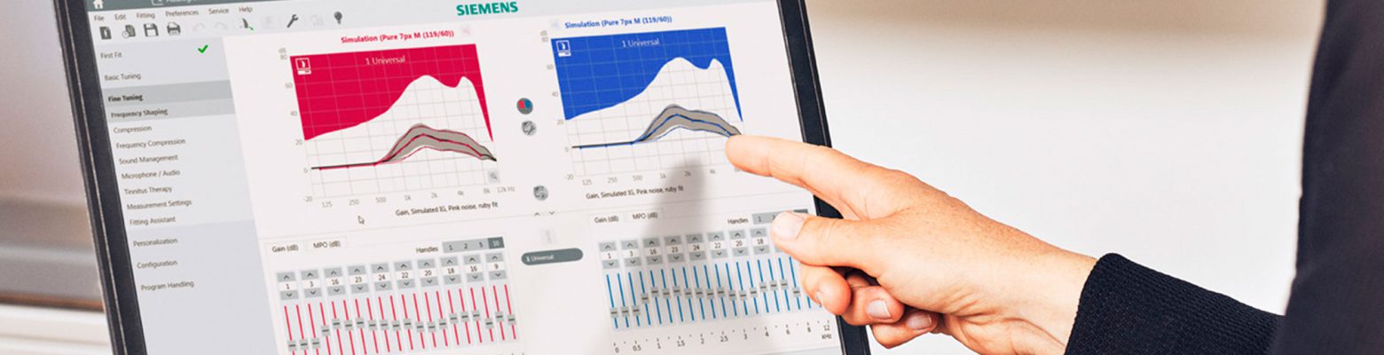
AutoFit™ is a beneficial feature in the Connexx™ Fitting Application that automatically provides the Hearing Care Professional (HCP) with an optimized real-ear insertion gain (REIG) setting without the need for the HCP to manually match targets. This paper describes how to perform quick match-to-target fittings using AutoFit from Connexx Version 8.5 onwards. Earlier versions of Connexx provided AutoFit functionality for selected REM equipment. Now the new IMC2 standard expands the range of REM equipment which supports AutoFit, starting from Connexx version 8.5 and Noah 4.5.1 or higher.
Steps to follow:
Set up REM system for probe microphone measurements, also check also preferences in Connexx.
AutoFit is a beneficial feature in the Connexx Fitting Application, which has been available for many years. AutoFit automatically provides the Hearing Care Professional (HCP) with an optimized real-ear insertion gain (REIG) setting, without the need for the HCP to manually match targets. AutoFit provides significantly faster real-ear verification for prescriptive targets (e.g. NAL-NL2 or DSL5), as well as offering the ability to verify Signia proprietary targets. The AutoFit procedure is time efficient and can save the HCP a considerable amount of time compared to manually matching to target during real-ear verification[i].
Compatibility
AutoFit is compatible with all levels of Signia hearing aids supported by Connexx. Connexx versions lower than 8.5 support AutoFit with a limited range of probe-microphone equipment, by using a proprietary communication protocol. With the introduction of Noah 4.5.1 HIMSA issued a new, reworked IMC2 communication standard, which is supported from Connexx 8.5 onwards (in addition to the existing proprietary protocols). More IMC2 compatible REM modules will be included step by step, so that most modern probe measurement equipment will be supported in the future. To see the latest list of supported IMC2 REM modules, check HIMSA web page on:
https://www.himsa.com/en-us/products/noahmodules/imccompliantmodules.aspx
Running Connexx 8.5 under Noah 4.5.1 or higher
AutoFit is available for the following IMC2 real-ear measurement (REM) modules:
and for the following dedicated REM devices (using proprietary protocols)
Running Connexx 8.5 stand-alone
AutoFit is available for
Benefit of Noah IMC2 compatible REM modules
The IMC2 protocol allows more extensive data exchange between the Fitting module and the REM module. For example, binaural REM measurements, RECD measurements, and coupler based automatic fittings can be performed from the Fitting module without opening the REM module. The availability of IMC2 features depends on the capabilities that the REM module provides, as well as the implementation of these features in the Fitting module.
[i] Hinchcliffe, S. (2012). Can AutoFit REMs improve Workflow? Poster presented at the conference of the British Academy of Audiology (BAA).
Hardware Set-up
When using AutoFit, the patient and hardware set-up is equivalent to traditional real-ear measurements and should be performed in the same way as recommended by the measurement system manufacturer. As for traditional real-ear measurements and match-to-target procedures, the success of AutoFit depends on the correct placement of the probe microphone tube, as well as the patient and speaker arrangement.
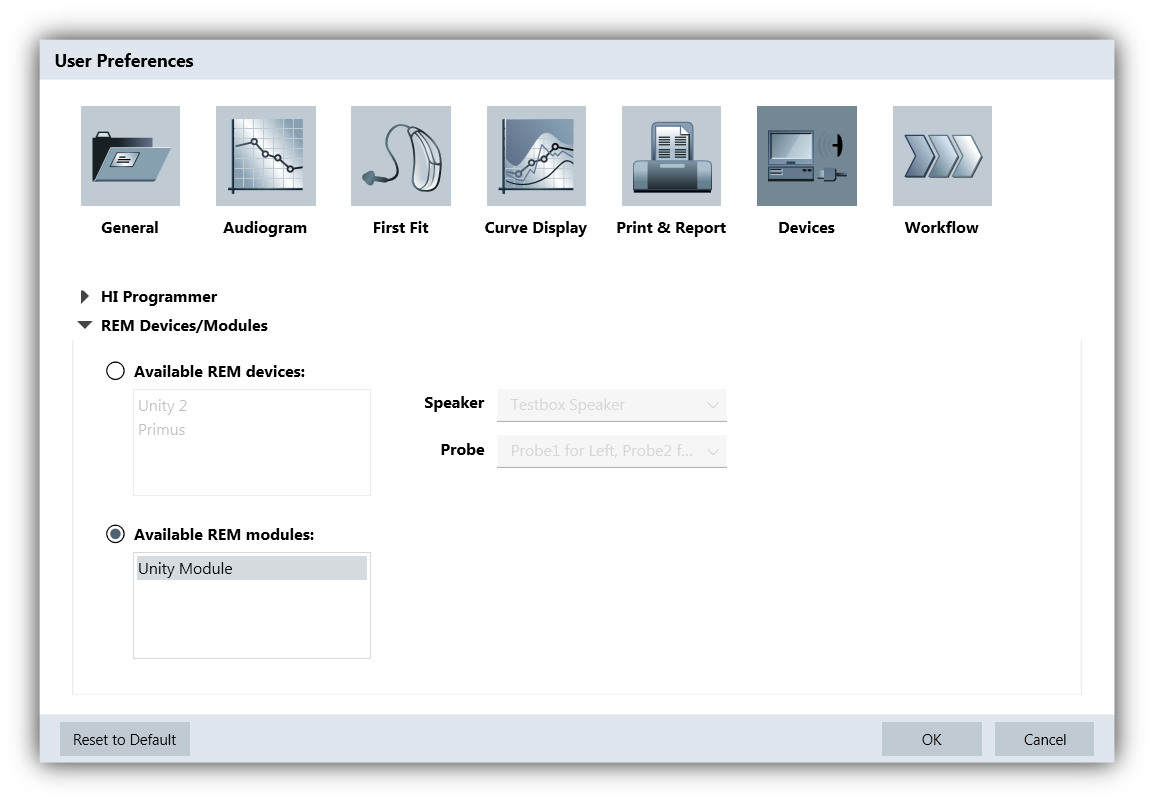
To select the measurement device used for AutoFit, open Connexx and go to “Preferences”. In the “User Preferences” window, select the “Devices” section and then open the “REM Devices/Modules” (Figure 1).
Select the REM device or REM module (=IMC2) you would like to work with. Only IMC2 compatible REM modules that are installed on your computer will be shown.
If you are working with a REM device which is not IMC2 compatible but is listed in the section “REM devices”, you might need to select the Speaker output or Probe headset.
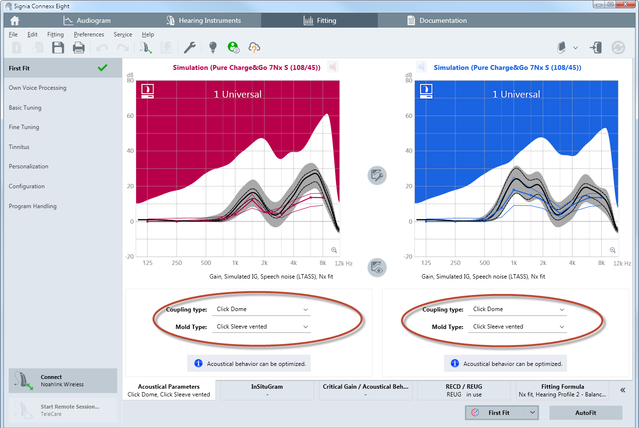
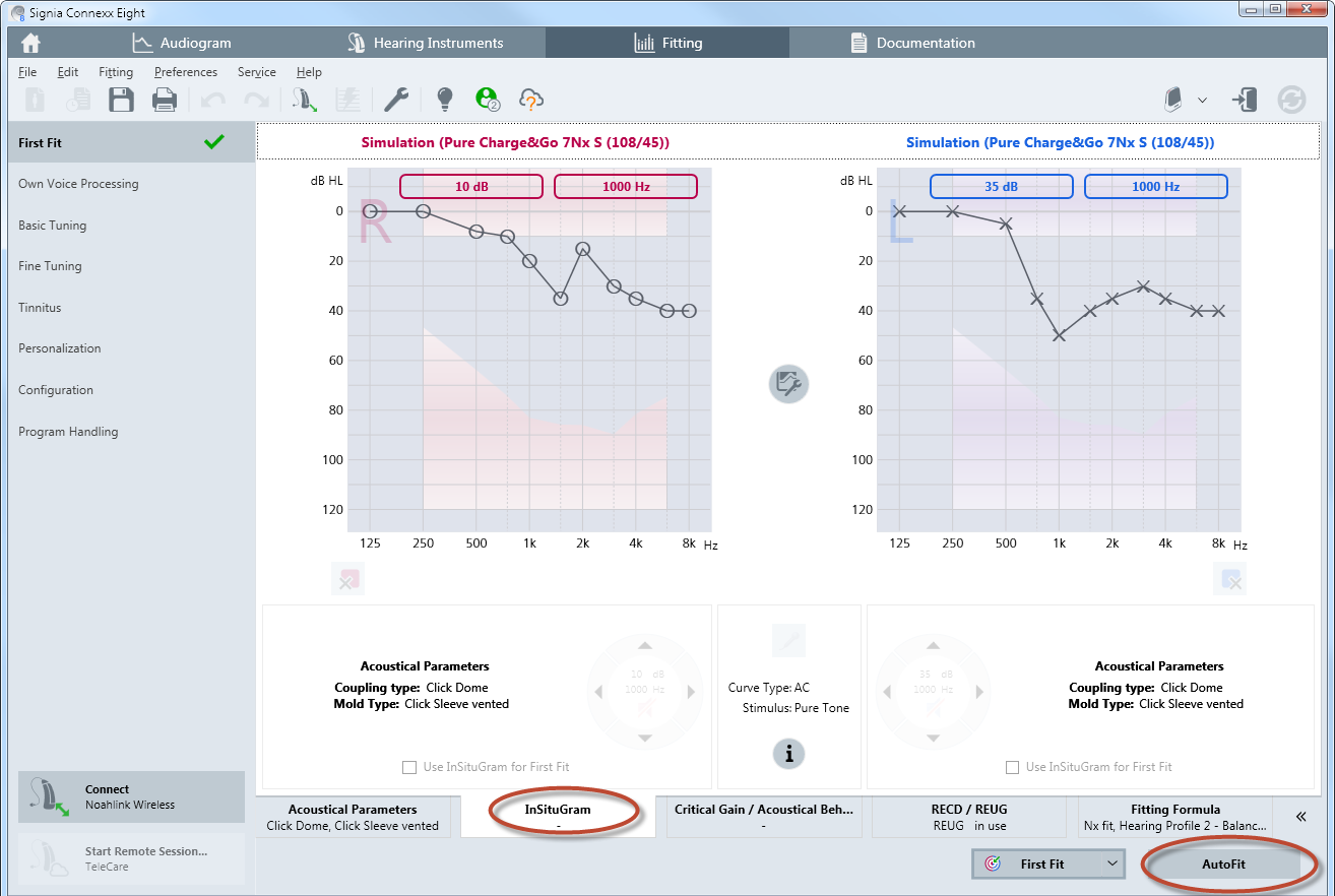
To access AutoFit, connect and read out the hearing instruments. It is vital that the appropriate acoustical parameters are selected in Connexx prior to commencing AutoFit (Figure 2). This includes coupling type (Life tip, dome or mold), ear hook, tubing, and vent size. . At this point, the HCP can use the hearing aids to perform an InSituGram™ from Connexx, if no pure-tone audiogram is available (Figure 3).
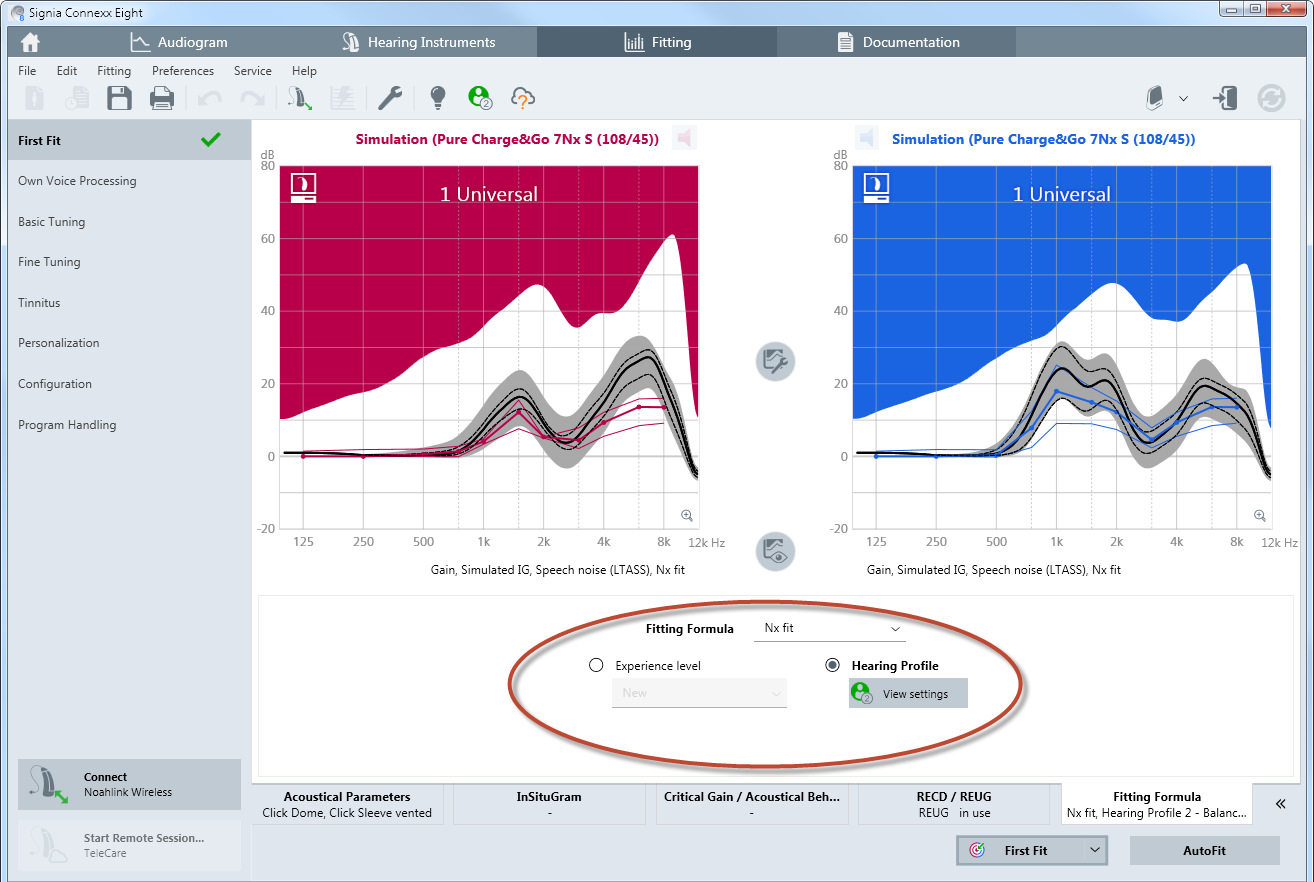
Before starting the AutoFit procedure, the desired prescription formula and user experience level should be selected. There is a choice of 1/3 gain, NAL-NL1, NAL-NL2, DSL-v5 and proprietary fitting formula as e.g. Nx-Fit (Figure 4).
To open the AutoFit window, click on “Autofit”. You will find this on the bottom right corner of the First Fit page. Importantly, this tab will only appear if compatible hardware is installed on the system and the hearing aids are connected or used in simulation mode (Figure 5).
The AutoFit procedure requires four steps to be fulfilled; these are displayed in four tabs across the bottom of the AutoFit screen:
“Tube Calibration” -> “REUG”, -> “AutoFit” -> “Verification”
In the tab “Verification” run a real-ear measurement with the input signal set to 80 dB. This will show that the 80 dB targets are adequately matched.
2.1. Probe-Tube Calibration
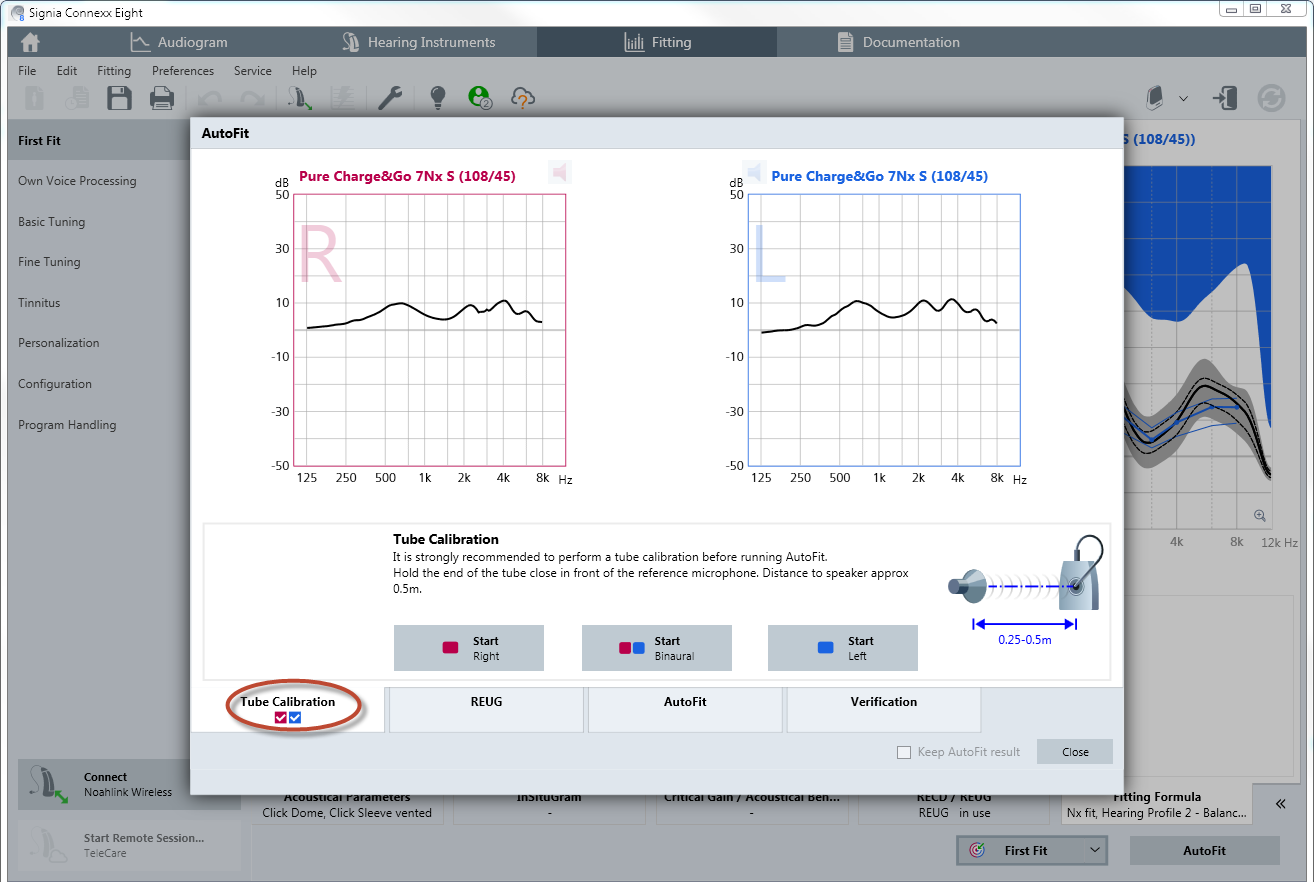
In the first tab “Tube Calibration” up to three “Start” buttons are shown, as some probe systems have separate probe-mic assemblies for the right and left ears. IMC2 compatible REM modules allow calibration to be performed simultaneously for both probe tubes. Follow the instructions provided by the REM device manufacturer to set up the real-ear measurement system correctly for Probe Tube Calibration.
In case tube calibration is performed for both sides simultaneously, make sure that the reference microphones of the probe-mic assemblies are held together as closely as possible without blocking the sound entering the reference microphones. This is necessary because often only one reference microphone is used during the calibration measurement.

The probe-tube calibration is necessary before the real-ear measurement is performed. If you are using a different probe assembly for the right and left ears, then both will need to be calibrated separately. Click either on “Start Right” or “Start Left” or “Start Binaural” to initiate the measurement. Follow the instructions shown on the Connexx screen regarding the calibration. Connexx will automatically check if the calibration is within the tolerable range.
Once the probe-tube calibration is finished, a checkmark will appear in each of the side-identifying boxes. Importantly, if the probe tube is altered during the testing (e.g., because it becomes perforated or plugged), the calibration procedure must be repeated with the new probe tube (Figure 6).
Once the probe-tube calibration is finished, a checkmark will appear in each of the side-identifying boxes. Importantly, if the probe tube is altered during the testing (e.g., because it becomes perforated or plugged), the calibration procedure must be repeated with the new probe tube (Figure 6).
2.2. Real-Ear Unaided Gain (REUG)
Because AutoFit is designed for the hearing aids to match Insertion Gain targets in the real-ear, a Real-ear Unaided Gain (REUG) measurement needs to be carried out together with the client. Confirm that the ear canals are free of any obstacles and that the eardrum is transparent and not perforated. If you suspect any contraindications that may hinder the following steps, ask the client to see a ENT-doctor to get the ear checked before proceeding.
Tipps for conducting the REUG:
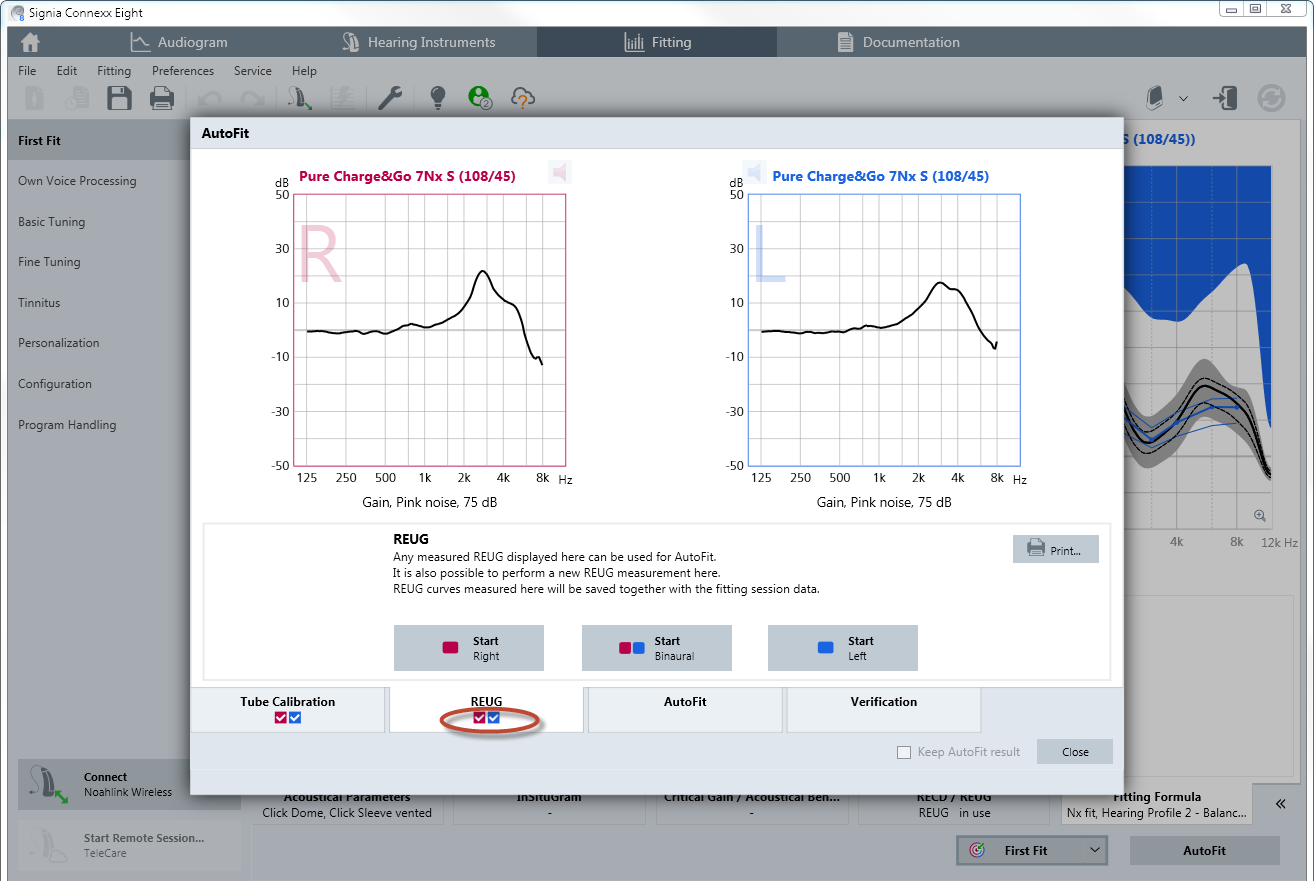
What is shown in Figure 7 is the REUG of a sample patient. After the measured REUG is displayed, a check mark appears in the respective identifying box (see red circle in figure). If the REUG measurement does not appear correct (e.g., the patient moved, the probe tube not was not inserted deeply enough, etc.), it is possible to remeasure the REUG after making the appropriate corrections by clicking on the “Start” button of the respective side. For bilateral fittings, it is of course necessary to measure the REUG of each ear independently. Connexx will guide you through the workflow accordingly.
2.3. Real-Ear Insertion Gain (REIG)
Once the REUG measurement has been performed, keep the probe tubes placed in the ear and carefully insert the mold, the dome, or the custom instrument into the ear. While inserting the mold, keep the probe tube still with your fingers so that the probe tube does not move in the ear canal.
Now click on the third tab “AutoFit”. The gain targets for the selected prescriptive formula will be displayed for soft, medium and loud inputs (50, 65 and 80 dB). The target for 65 dB is drawn with a thicker line with filed circles (Figure 8).
During AutoFit, the hearing aids will be switched to “Test Settings” automatically. This prevents adaptive features such as directional microphones and noise suppression from affecting the result.
Open fittings
If you are fitting open domes or molds with bigger vents (> 2mm) the fitting might be influenced by sound leaking from the hearing instrument speaker, out of the ear canal, and into the reference microphone of the probe assembly. The adaptive leveling and equalizing process during the room equalization procedure could therefore be influenced by the sound leaking from the ear canal, which could in turn affect the validity of the measurement signal. Therefore, Connexx will automatically mute the hearing instrument output during the room equalization procedure. This can be observed during the AutoFit procedure, where the speaker icons for each hearing instrument are initially muted and subsequently unmuted when the measurement starts.
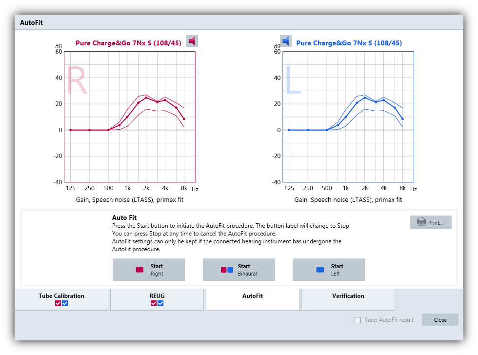
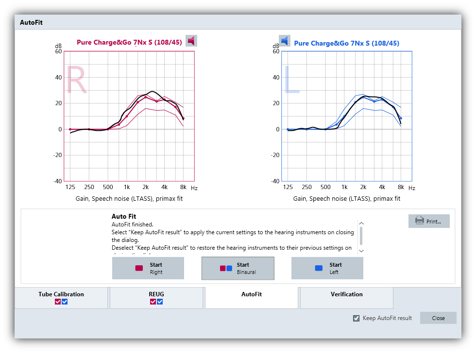
AutoFit
To begin the procedure, click on one of the “Start” buttons. AutoFit is either performed for both hearing aids together (recommended) or performed for each hearing aid separately. The REM device will first emit a device specific signal to perform the room equalization. When this signal is played, the hearing aids will be muted. After a few seconds the signal will change to an LTASS (long term average speech signal) based signal with 65dB SPL, which allows the AutoFit algorithm to determine the current gain inside the wearer’s ear, and then automatically adjusts the gain to match the selected prescriptive target for the 65 dB SPL input level. The target match is performed in several steps and applied to each side separately. Wait until the application tells you that AutoFit is finished. The results of this automated fit-to-target process are displayed in Figure 9.
Verification
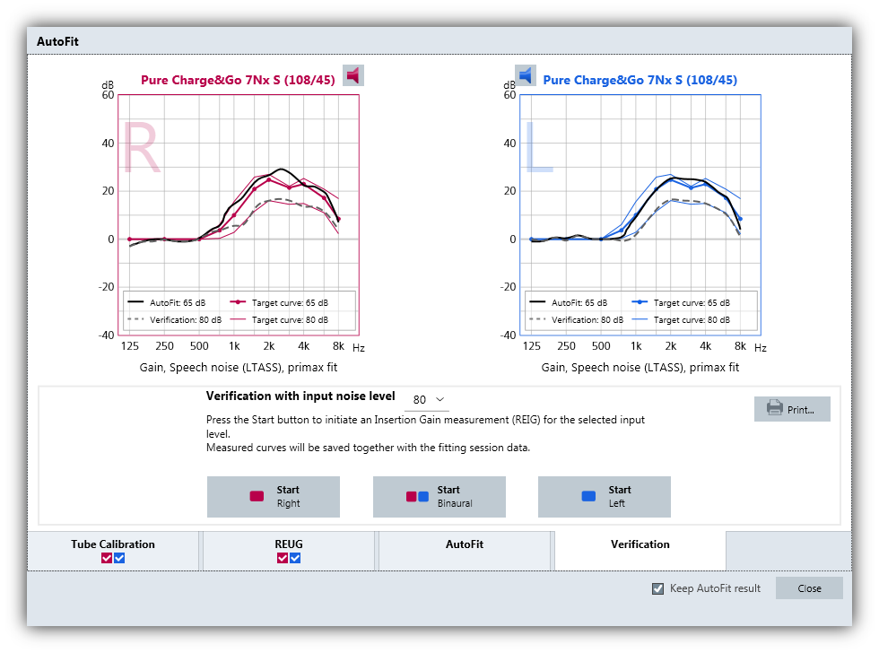
After the 65 dB input has been automatically matched, the final step is to verify the hearing instrument gain for high input levels. To perform this step, click the “Verification” tab. For the verification, the level is set to 80 dB. Low level input verification can optionally be performed afterwards with 55 dB input signal.
Click on the “Start” button to initiate the REIG measurement with an 80 dB LTASS signal. The curves are measured and will be displayed as dashed grey lines. No further corrections will be applied. These lines should match the 80 dB target, which is the lower of the two thin target lines. Figure 10 shows an example of a fitted and verified pair of hearing instruments.
After AutoFit is complete, the HCP is given the option to program the AutoFit settings into the hearing instruments by leaving the “Keep AutoFit result” tick box checked, or alternatively, restoring the instruments to the previous settings (before performing AutoFit). Accordingly, follow the instructions given in the AutoFit window.

Joachim Baumann started his career in 1989 as a developer for electronic circuits for cochlea implants and wireless charging technology for a fully implantable hearing instrument. In 1998, he became responsible for functional testing during surgery and post-operative care and fitting of the implants during clinical studies in cooperation with the ENT Clinic of the University of Tübingen.
He joined Siemens Audiologische Technik (now Sivantos GmbH) Corporate Product Management team in 2001 and took over the Product Management for Diagnostic Measurement System Unity and other equipment. He was responsible for the global launch of the Unity 2 system in 2004 and the successor product Unity 3 in 2014. He collaborates with the HIMSA, IMC2 working group.
Joachim holds a diploma ( Dipl.-Ing. equivalent to MSc) in Electronic engineering, Electroacoustics and Psychoacoustics from the Technical University of Munich, Germany.